Customer: Thales Alenia Space
Location: Jurong Camp, Singapore
Hardware: Thales Alenia Space Ka-band antenna & TCI International HF Antenna
Challenge:
To understand the impact of Thales Alenia Space Ka-band antenna on existing TCI HF systems in the spurious domain. This study looks at how this could be mitigated to allow the two systems to exist in harmony.
NB. when an HF antenna fires at the Ka-band dish antenna it results in the re-radiation and interference with the HF antenna.
Approach:
The study compares the calculations undertaken by ATDI and those from Thales (Ka antenna manufacturer) to provide a complete overview of the potential interference. The study was undertaken at the Jurong Camp in Singapore, with HF transmitters and SAT sites outlined below:
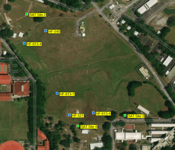
This configuration caused changes in the radiation pattern shape and gain of the HF antenna. It operated at 11 and 22 MHz at resonant frequencies, with currents at their strongest causing the greatest interference with the HF antenna pattern. The distant frequencies and the currents induced in the Ka-band antenna were much smaller, and in turn, the impact on the gain and pattern shape changes were smaller.
Crude estimates of the effect of the Ka-band antenna could have been applied using a simpler computer model where the dish and the HF antenna were represented by simple dipoles. However, for the purposes of this study, the end-user wanted ATDI to undertake a full analysis using its RF engineering tool and supported by high-resolution digital maps. The maps used were 2m DTM, 2M clutter (land cover) and buildings layer, with aerial maps from a WMTS service (Google or Bing maps).
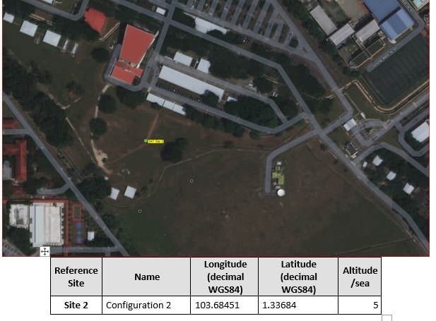
For the purposes of the study, one Ka site antenna was selected, as shown below:
Once the technical parameters were aligned for the two systems, an interference compatibility calculation was undertaken. Using the spurious limits set by the ITU, the HF system thresholds were calculated. Fields strengths for HF antennas must be less than these thresholds. To support these calculations, spurious maps were computed at 4MHz, 10MHz and 30MHz with the Ka antenna orientated at 90° and 270°.
The Spurious power radiated by the Ka antenna in the HF was defined according to recommendation ITU-R SM.329 Spurious limits for antenna transmission lines. A margin of 3dB was added for the exclusion area. The image below shows the Spurious power received exceeding these thresholds:
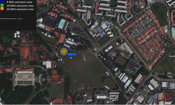
Using the results from these calculations, exclusion zones were set up for HF antennas for up to 30MHz, identifying areas which could not be protected.
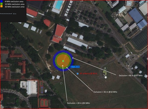
The spurious power radiated by the Ka antenna was defined according to Thales measurements, which look at the separation distance between the Ka antenna and the HF 540 antennas at 85m. The maximum threshold degradation set by the ITU-R SM.329-12 meant field strengths received at the HF antenna = 3 dBµV/m, as shown below.

This was compared to the Thales measurements, which showed a field strength received at the HF antenna = 51 dBµV/m, as shown below.

The study also considered the construction of new buildings proposed near the Ka antenna. By adding the new building sites, ATDI were able to compute the interference from reflections. HTZ Warfare features a Buildings Reflected Signals function, which performs interference analysis based on threshold degradation at the HF receiver.
The study was carried out using HTZ Warfare, ATDI’s flagship battlefield spectrum engineering software
Solution:
The analysis was undertaken over three locations with the maximum signal reflected and the sum reflected signals generated. The outcomes of this analysis saw unwanted emissions in the spurious domain computed using less stringent spurious power in 10 kHz bandwidth and with an HF antenna gain at 0 dB was considered the worst case of interference.
Based on ITU-SM 329-12 method (maximum permitted spurious domain emission power), the Ka antenna could affect the system gain of the closest HF antenna by 0.5 dB.
Based on Thales measurements (-150 dBW/4 kHz), the Ka antenna cannot affect the system gain of the closest HF antenna.
ATDI recommended not to build in area B (see full report), even if the threshold degradation on the HF receiver will be very low (<= 0. 03 dB).
The study was completed using HTZ Warfare.
Electromagnetic interference (EMI) versus Radio Frequency Interference
Noise in RF systems is generally considered as any RF energy that is not the desired signal. Two terms commonly used to describe RF noise are Electromagnetic Interference (EMI) and Radio Frequency Interference (RFI). EMI is random, broadband noise whereas RFI is narrowband noise broadcast at specific frequencies. EMI is generated by non-broadcast electronic devices and electric motors. The noise emitted by these devices is a by-product of their operation. EMI may enter a wireless microphone or IEM system via the antenna, transmission line, or power connection, and the effect is typically high-frequency noise or distortion. RFI differs in that it is not unintentionally radiated energy at random power levels, but rather the presence of unwanted RF signals broadcast by RF transmitters. Sources of RFI may include other wireless microphones and IEMs, radio and television broadcasts, wireless communications systems, or consumer electronic devices with wireless functionality.

